Wee-Things: Using LEDs
Using actual LEDs
Ping out:
Common anode LED, four legs. Wire the longest one to Vout. The other three to the following pins: 3, 5, 6. We can't use 4 since is an onboard LED.
The gpio pins in the NodeMCU board all digital, which means that we can do on/off but not control the brightness which we could do with an analog signal.
_[''''']_
---------
 | | | |
 | | | |
 R | G B
   Vin
ASCII: pin layout
The wiring:
Vin => 3.3v
R => 6
G => 7
B => 5
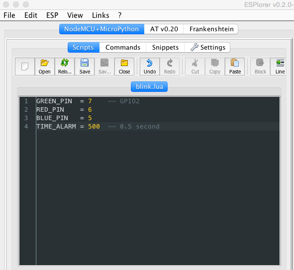
We are going to create three global variables and assign them a pin port number, we will later wire the corresponding legs of the LED to this ports.
RED_PIN    = 6
GREEN_PIN  = 7
BLUE_PIN   = 5

gpio.mode(RED_PIN, gpio.OUTPUT)
gpio.mode(BLUE_PIN, gpio.OUTPUT)
gpio.mode(GREEN_PIN, gpio.OUTPUT)

Snippets
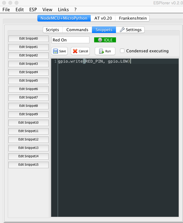
We can use the snippet feature of ESPLorer to control the on/off status of an RGB LED.
Snippet to turn Red On:
- Click Edit Snippet 0
- Paste:
gpio.write(RED_PIN, gpio.LOW) - Rename to: Red On

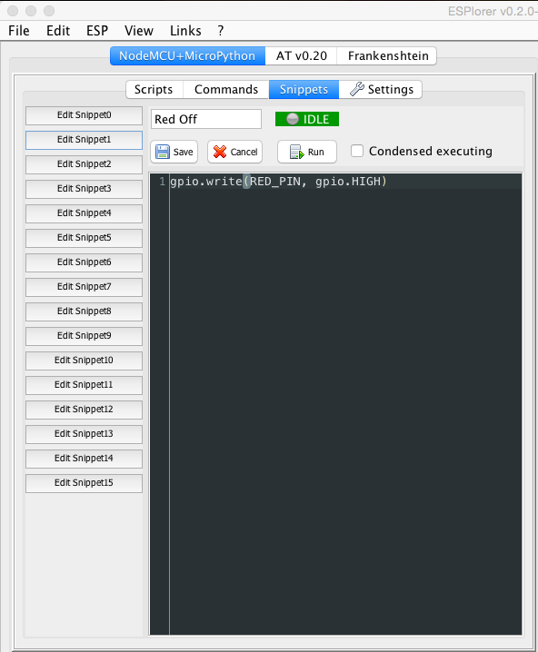
Snippet to turn Red Off:
- Click Edit Snippet 1
- Paste:
gpio.write(RED_PIN, gpio.HIGH) - Rename to: Red Off

The rest of controls are pretty much the same, just changing the name of the ping we are going to address.
Click Edit Snippet 2
Paste:
gpio.write(GREEN_PIN, gpio.LOW)Rename to: Green On
Click Edit Snippet 3
Paste:
gpio.write(GREEN_PIN, gpio.HIGH)Rename to: Green Off
Click Edit Snippet 4
Paste:
gpio.write(BLUE_PIN, gpio.LOW)Rename to: Blue On
Click Edit Snippet 5
Paste:
gpio.write(BLUE_PIN, gpio.HIGH)Rename to: Blue Off
Then, we should see the snippets appear on the bottom right corner of the IDE:

